Door Check, Temperature and Humidity using ESP8266 NodeMCU
We have two garages on our home. The one in the back has two doors - the larger door to bring in cars and such and a regular entrance door on the side. As it happens sometimes we forget to close them. That means going all the way out there to check them. I was playing around with an ESP8266 and had the thought that I could do something with that to let me know if either of the doors was open.
That's what started this project. I found some magnetic door switches on line that would be pretty easy to interface to the ESP - they're just switches. I hooked them up to D1 & D2 (pins 4 & 5) and set them as input - pullup. Then tied the other end to ground. It works great. The ESP can take 7v - 12v on VIN so I grabbed one of the wall plugs from an old phone system and used that as the power supply. You can see the setup in image 1 and image 2.
You may also notice the little greenish/blue thing attached to it. That is a DHT11 temperature and humidity sensor. I picked those up from Adafruit.com for $5/each. I could have gotten more accuracy with a DHT22 but it's a garage - do I need more than 2% accuracy on the temp? and more than 5% on the humidity? Pretty much sure I don't. Also the range on the DHT11 is 0-50c (32F to 112f). Didn't need better than that.
So for $5 more I would not only know if the doors were open but also what the temperature and humidity were - couldn't pass that up.
Image 6 shows the corner of the garage with the two doors and on the shelf on the left side where mounted the ESP. The 440 Volt sign was already there - someone gave it to me years ago and I use it as decoration - but maybe this will keep people from screwing with the ESP 🙂
You could use other material to mount things on but I decided to make a 3d printed mount board. I used Openscad (https://www.openscad.org/) to design the piece and create the STL file included here. There are 4 files. I designed and printed one with the pin-out lettering on the board but when I reduced the size to make room for the components the letters didn't print properly. They printed fine in the larger size (image 7, top). The SCAD file is included if you want to play around with it and get them to print. I ended up using a blank board. The mounting holes fit the 8 terminal board I used - if you get a different one you may have to move the holes around a bit. It's a pretty straight forward print - just use your general printer settings, I used ABS.
Image 5 is the small entrance door and image 4 the switch on the side of the 10' door. Image 1 and 2 is how I tested things on the bench.
Here's how the web page will look:

Read the code on how to use the WIFI manager. If you uncomment this line:
wifiManager.resetSettings();
When you restart the ESP it will go into the configure mode and you can pick the wifi and set the password. Run the configure then comment the line and download it and it will continue to use that wifi point and password as long as it's available.
At a minimum I used these two sites for reference:
http://randomnerdtutorials.com
https://github.com/tzapu/WiFiManager
Wiring is simple - connect one side of each switch to GND. The other side of one switch goes to D4, the other to D5. Connect the power supply (7v -12v) to GND and VIN. The DHT11 - goes to GND, the + goes to 3.3V (NOT VIN). The output goes to D3 of the ESP. That's it.
Any questions - send them along. I have the code in ZIP format HERE.
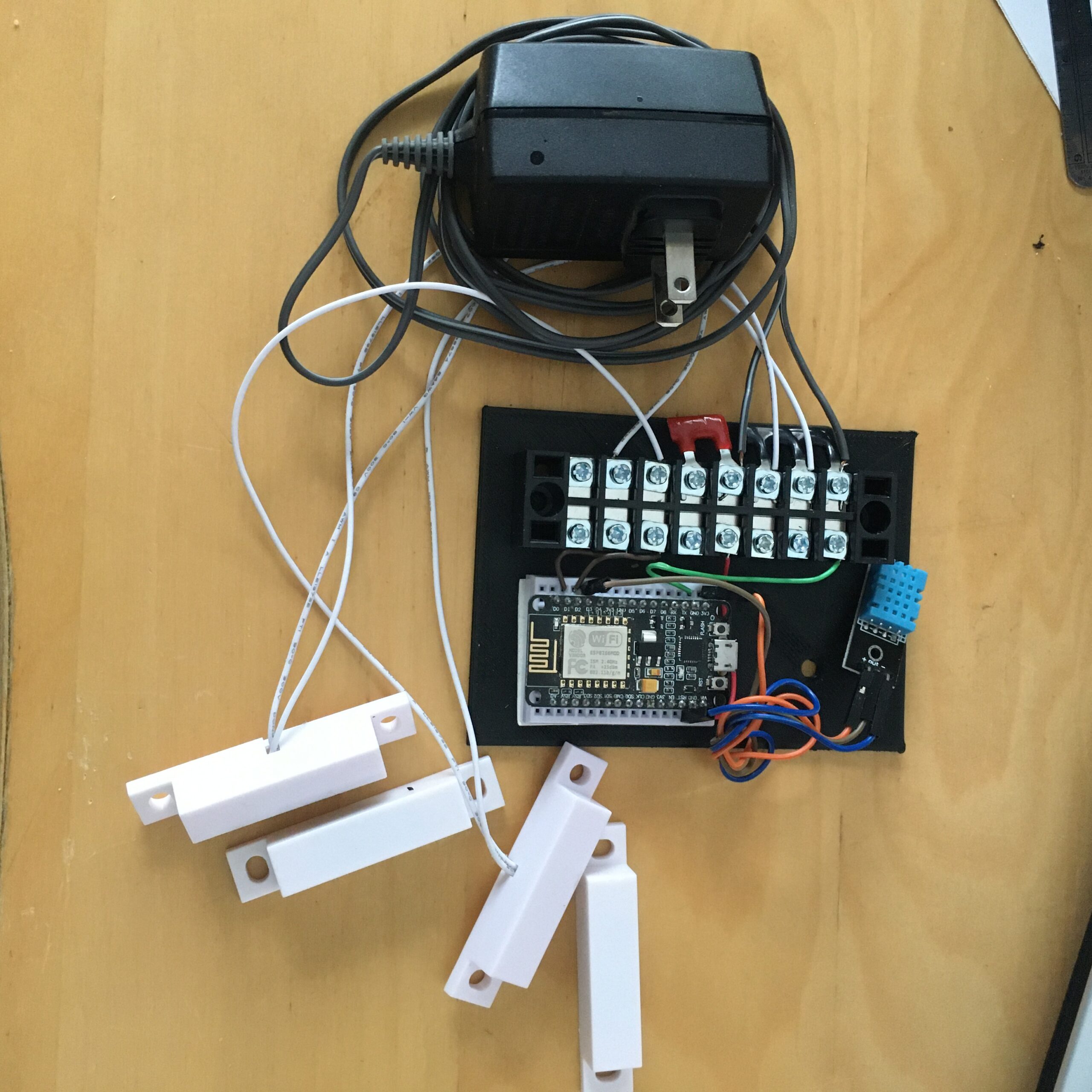
image 1
full view
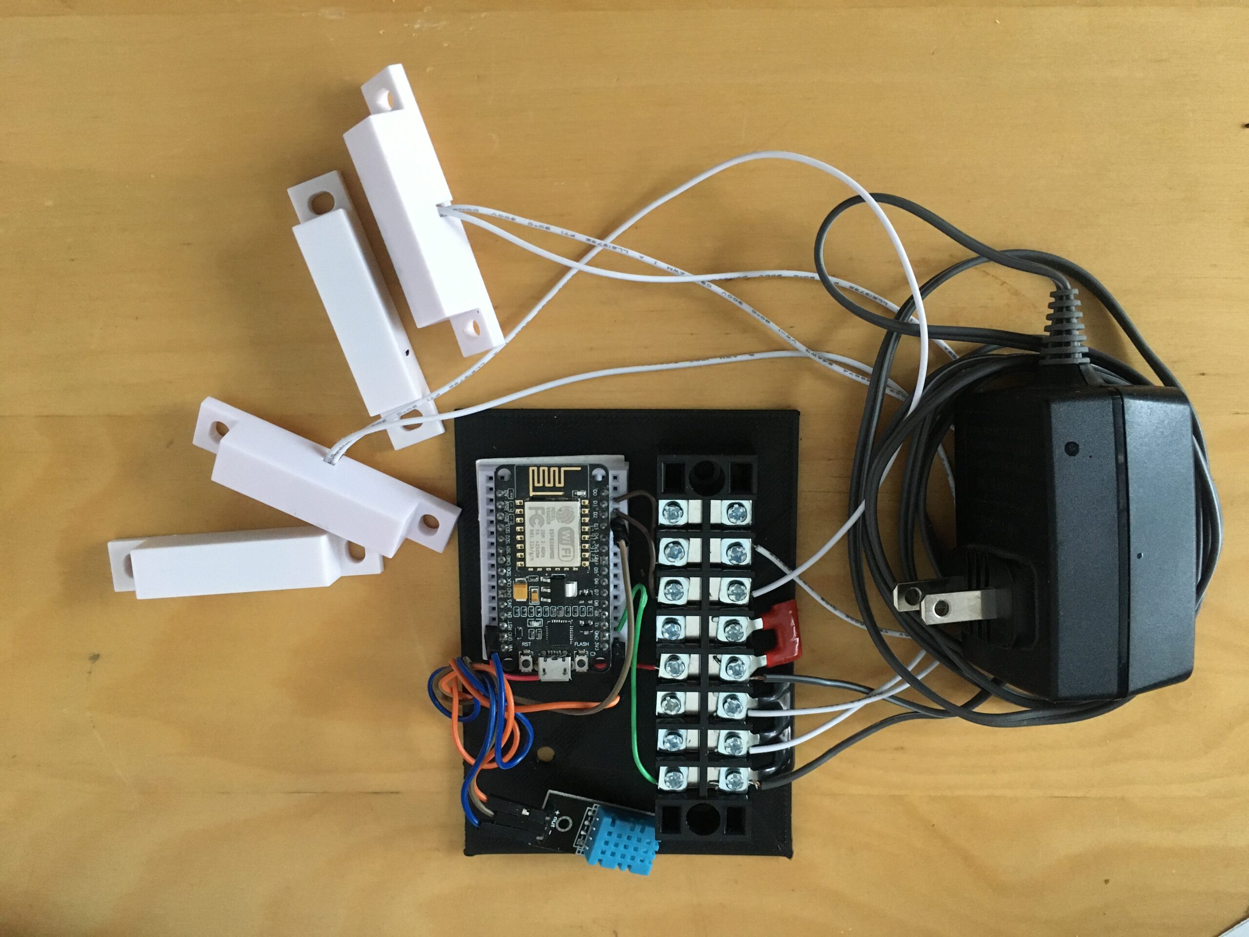
image 2
Fully view 2

image 3
Mounted on the Wall
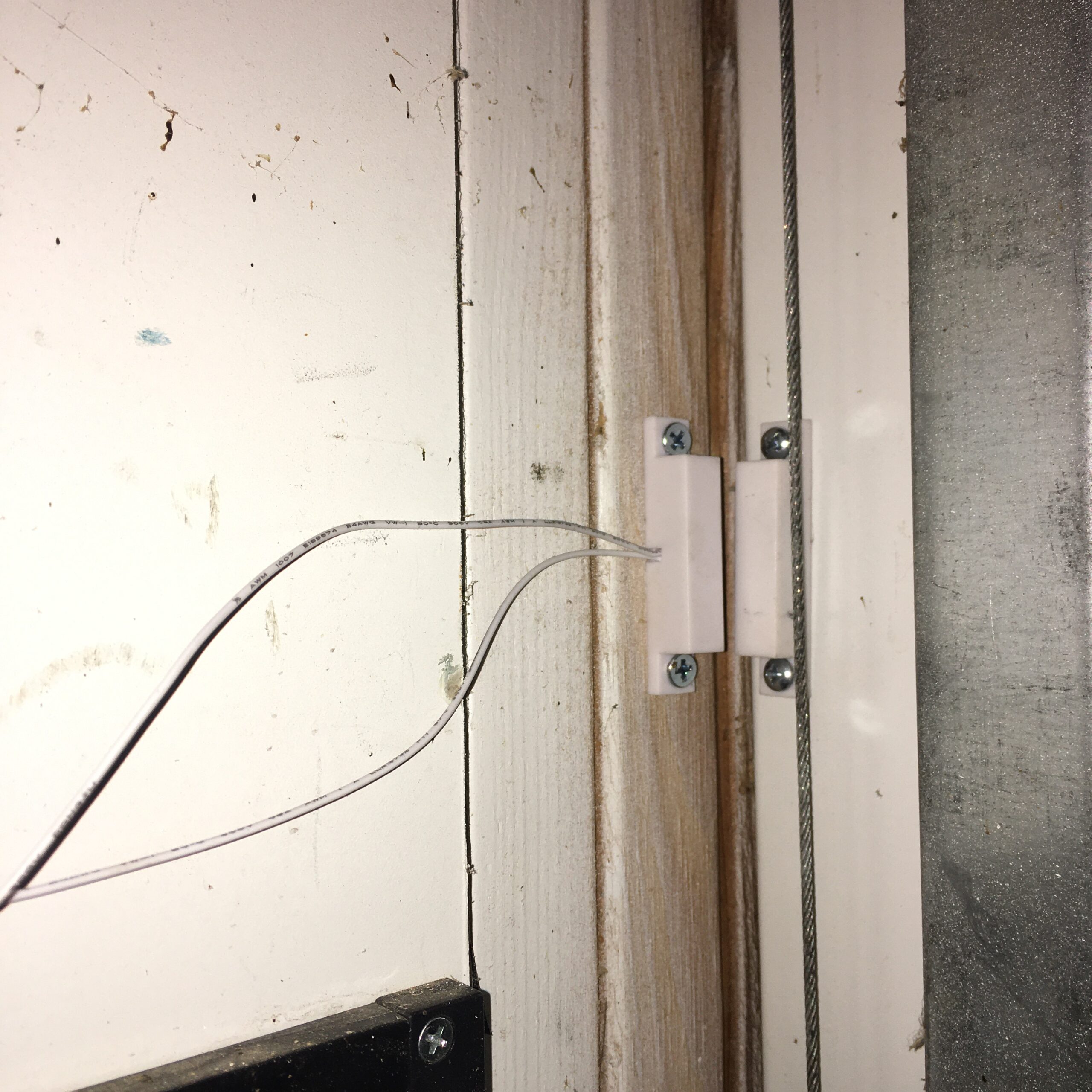
image 4
Big garage door mount

image 5
Small door mount
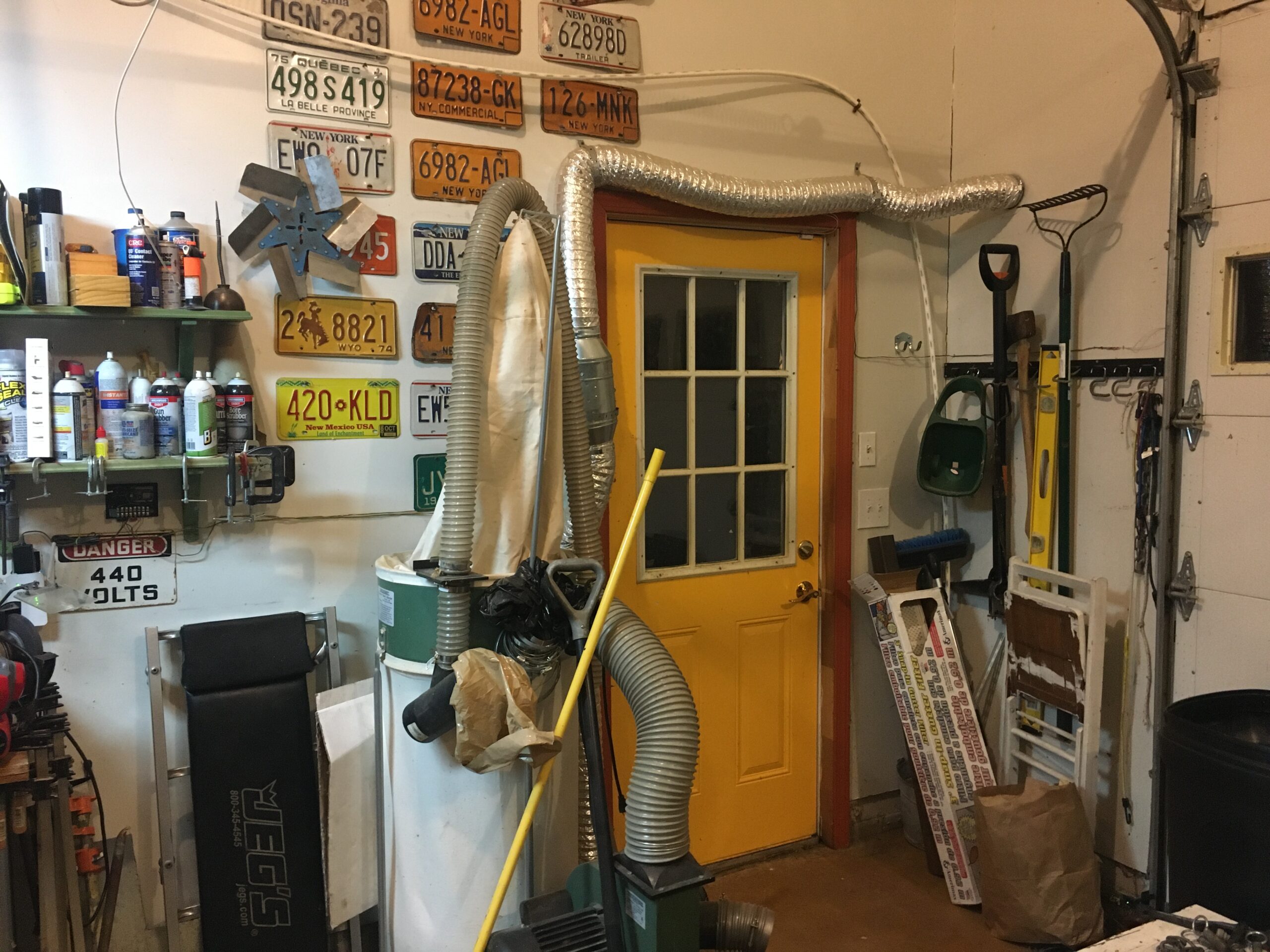
image 6
Doors and mount location

image 7
3d printed mounting plate